| Home | Energy Physics | Nuclear Power | Electricity | Climate Change | Lighting Control | Contacts | Links |
|---|
INTRODUCTION:
This web page describes the basic structural elements of a spheromak.
SPHEROMAK CONCEPT:
The existence of quantum charged atomic and nuclear particles with stable amounts of energy is enabled by the existence of a natural quasi-toroidal shaped electro-magnetic structure known as a spheromak.
A spheromak has a toroidal magnetic field inside the quasi-toroid shaped surface and has both a poloidal magnetic field and a radial electric field outside the quasi-toroid shaped surface. This quasi-toroid shaped surface is referred to herein as the spheromak wall. A spheromak has static charge inits core that reduces the spheromakinternal electric field to zero.
SPHEROMAK EXISTENCE:
Spheromaks physically exist and have been photographed in plasmas. They anecdotally exist as ball lightning that has been ocassionally observed in the proximity of high altitude aircraft. They are the charge and electro-magnetic fiel structures that enable the existence of stable quantum charged particles such as electrons and protons and enable absorption and emission of photons by these particles.
SPHEROMAK COMPONENTS:
The essential components of a spheromak are: a single layer quasi-toroidal closed filament path defining a spheromak wall through which a constant charge per unit length circulates at the speed of light, internal toroidal magnetic field energy, external poloidal magnetic field energy and external radial electric field energy. The combined field energy density at the inner surface of the spheromak wall must everywhere exactly equal the combined field energy density at the outer surface of the spheromak wall.
SPHERMAK WINDING CONCEPT:
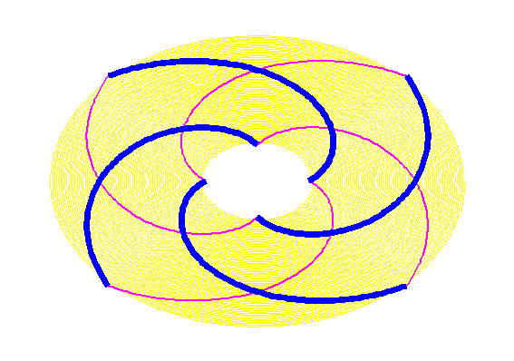
An approximate plan view of the filament path of a theoretical elementary spheromak with three poloidal turns (Np = 3) and four toroidal turns (Nt = 4) is shown below to illustrate a winding with a both poloidal and toroidal turns. The blue lines show the current path on the upper face of the spheromak. The red lines show current path on the lower face of the spheromak. Note that the current path never intersects itself except at the point where the winding closes so that the current can retrace its previous path.
In the diagram yellow shows the region of toroidal magnetic field. Outside the yellow region is a poloidal magnetic field. Bpth regions contain radial electric fields.
When the spheromak filament has passed through the spheromak central hole Nt times it has also circled around the main axis of spheromak symmetry Np times, and has reached the point in its closed path where it originally started.
This elementary spheromak winding pattern was generated using a polar graph and formulae of the form:
R = Rc + K [t - t(2N)] where t(2N) = (2 N) (3 Pi / 4) and t(2N) < t < t(2N+1)
and
R = Rs - K [t - t(2N + 1)]
where:
t(2N + 1) = (2N + 1)(3 Pi / 4)
and
t(2N + 1) < t < t(2N + 2)
where:
N = 0, 1, 2, 3.
Use:
Rc = 1000,
Rs = 4105,
K = (4140 / Pi)
Top to bottom connection points were depicted by adjusting the torus Rs to 4045 and Rc to 1060.
SPHEROMAK PHOTOGRAPH:
A photograph of a real plasma spheromak taken by General Fusion circa 2012 is shown below:
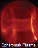
More plasma spheromak photographs are shown in the paper:
Spheromak formation and sustainment studies at the sustained physics experiment using high-speed imaging and magnetic diagnostics by Romero-
Talamas et al , Physics of Plasmas, vol.13 (2006).
LOCATION IN A SPHEROMAK:
A spheromak wall has cylindrical symmetry about its main axis of symmetry and has mirror symmetry about its equatorial plane. Any position in a spheromak cross section can be defined by:
(R, Z)
where:
R = radius from the main axis (Z axis) of cylindrical symmetry;
and
Z = height above (or below) the spheromak equatorial plane.
GEOMETRICAL FEATURES OF A SPHEROMAK:
Important geometrical features of a spheromak include:
Rc = the spheromak wall inside radius on the equatorial plane;
Rs = the spheromak wall outside radius on the equatorial plane;
Ro = the radius of an imaginary ring on the spheromak wall where (dZw / dRw) = 0.
Note that Ro indicates the nominal linear size of a spheromak;
Ho = the spheromak wall height Zw above the equatorial plane at R = Ro;
Np = number of poloidal filament turns about the major axis of symmetry;
Nt = number of toroidal filament turns about the ring R= Rp, Z = 0.
The subscript c refers to spheromak wall inside radius (core) on the equatorial plane;
s refers to the spheromak wall outside radius on the equatorial plane.
SPHEROMAK CROSS SECTIONAL DIAGRAM:
The following diagram shows the approximate cross sectional shape of a spheromak.
Note that on this diagram:
y = Z and x = R
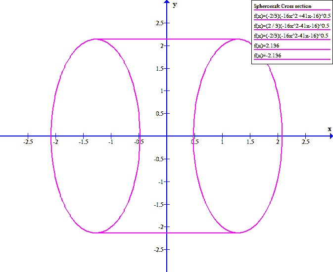
For this diagram:
Ho = 2.156
and
Rs = 2.156
and
Rc = 0.4802
Note that the cross section of a real spheromak is not round.
In this diagram on the main axis of symmetry is R = 0
for the purpose of drawing this diagram an elliptical spheromak cross section was assumed. In reality the spheromak cross section is more distorted.
It is shown at Spheromak Wall, that in cross section the spheromak wall has a distorted shape. In cylindrical coordinates the spheromak wall's Zw value peaks at R = Ro, Z = +/- Ho and intersects the Z plane at R = +/- Rc and at R = +/-Rs. The spheromak minor axis is at R = Ro, Z = 0.
Conceptually a spheromak wall is a quasi-toroidal shaped closed surface, with a distorted cross section,formed by the closed filament current path of a spheromak. This filament path defines the spheromak wall surface curvature. In plan view, looking along the Z axis, a spheromak wall is round at both its inner radius Rc and its outer radius Rs. In cross section, looking along the spheromak minor axis, the spheromak cross section is distorted with maximum width (Rs - Rc) and maximum height 2 Ho.
SPHEROMAK GEOMETRY:
The spheromak wall separates the region inside the spheromak wall from the region outside the spheromak wall.
The spheromak wall is cylindrically symmetric about the spheromak Z axis (major axis of symmetry) and is mirror symmetric about the spheromak's equatorial plane where Z = 0.
The spheromak wall is defined by a distorted toroidal shaped single layer filament winding carrying current I with net charge Q continuously circulating at speed of light C around a closed path of length Lh.
The filament's charge Q is uniformly distributed along the filament length Lh.
This filament winding contains a blend of Np poloidal turns around the spheromak major axis of symmetry (the Z axis) and Nt toroidal turns around the spheromak minor axis.
There are no filament winding cross overs.
The winding is stable in part because the integers Np and Nt are constant and share no integer factors except unity.
GEOMETRICAL PARAMETERS OF A SPHEROMAK:
Important geometrical features of a spheromak include:
Rc = the spheromak wall inside radius on the equatorial plane;
Rs = the spheromak wall outside radius on the equatorial plane;
Ro = the radius of an imaginary ring radius on the equatorial plane which indicates the nominal linear size of a spheromak;
Ho = the spheromak wall height above the equatorial plane at R = Ro;
Np = number of poloidal filament turns about the major axis of symmetry;
Nt = number of toroidal filament turns about the minor axis of symmetry.
The subscript c refers to spheromak wall inside radius (core) on the Z = 0 plane;
s refers to the spheromak wall outside radius on the Z = 0 plane.
The subscript o refers to values measured at R = Ro.
SPHEROMAK SCALING:
An important property of spheromaks is that they maintain the same relative geometry over changes in linear size. Hence Ho, Rs and Rc are all proportional to Ro.
The height to width ratio of the spheromak cross section is:
Ka = [2 Ho / (Rs - Rc)]
Note that Ka is independent of Ro. For a circle Ka = 1.
Let subscript f designate a value corresponding to Ro = Rof. Then:
Rs = Rsf (Ro / Rof);
Rc = Rcf (Ro / Rof);
Ho = Hof (Ro / Rof);
Rs - Rc) = (Rsf - Rcf)(Ro / Rof)
= Kb Ro
where:
Kb = (Rsf - Rcf) / Rof
The scaling factor is Kb.
Hence:
(Rs - Rc) = Kb Ro
It is convenient to define constant Kr by:
Kr = Rs / Rc = Rsf / Rcf
Then:
(Rs - Rc) = Kb Ro;
gives:
(Kr + 1) Rc = Kb Ro.
Thus as Ro increases both [Rs- Rc) and Ho proportionately increase.
The spheromak wall is formed by charge circulating at the speed of light C around a complex quasi-toroidal shaped closed filament path of length Lh which has both Np poloidal turns Nt and toroidal turns. The spheromak parameters Np and Nt are both integer constants independent of Ro.
One purely poloidal turn has length Lp where:
Lp = 2 Pi Ro Ca.
One purely toroidal turn has length Lt where:
Lt = [Ct Ro]
where Ct is a constant.
The length Lh of the closed spheromak filament is given by:
Lh^2 = (Np Lp)^2 + (Nt Lt)^2
Since Np and Nt are both constants independent of Ro and since both Lp and Lt are proportional to Ro, hence Lh is proportionl to Ro.
In summary, size of a spheromak's wall is defined by (Ro / Rof) and the shape of a spheromak is fully defined by Hof, Rsf and Rcf. The spheromak may be larger or smaller, as set by (Ro / Rof) but:
Kr = Rsf / Rcf
and
Hof / Rcf
remain constant.
Recall that:
Ka = [2 Ho / (Rs - Rc)]
= [2 Hof (Ro / Rof) / [(Rsf(Ro / Rof) - Rcf (Ro / Rof)]
= [2 Hof / (Rsf - Rcf)]
= [2 Hof / Rcf (Kr + 1)]
Note that the parameters:
Kr = Rsf / Rcf
and
Ka = 2 Hof / (Rsf - Rcf)
= 2 Hof / Rcf (Kr - 1)
are purely functions of fundamental physical and mathematical constants.
SPHEROMAK FIELDS:
The net charge Q circulates along a mixed toroidal and poloidal closed path defined by the filament winding that forms the spheromak wall.
For an isolated spheromak in a vacuum, at the exact center of the spheromak (at the origin) the net electric field is zero and the magnetic field is purely poloidal.
In the region inside the spheromak wall the magnetic field is purely toroidal.
On the Z = 0 plane inside the spheromak wall the radial electric field is:
[(So / Epsilono)(Ro / Rc)^2 (Rc / R)^2 = (So / Epsilono) (Ro / R)^2
On the Z = 0 plane outside the spheromakat R = Rs the radial electric field is:
(2 So / Epsilono)(Ro / Rs)^2
In the region outside the spheromak wall the magnetic field is purely poloidal and the electric field is radial being locally normal to the spheromak wall.
In the spheromak core where R < Rc the cylindrically radial electric field components cancel each other out leaving only axial electric field components which diminish to zero near the spheromak center at R = 0, Z = 0.
At R = Rs, Z = 0 and extending out to R = infinity the external electric field is spherically radial.
The circulating current forms a purely toroidal magnetic field inside the spheromak wall and a purely poloidal magnetic field outside the spheromak wall.
The net electric charge Q on the filament causes an electric field outside the spheromak wall normal to the spheromak wall surface.
At the exact center of the spheromak, due to spheromak symmetry, the electric fields all cancel to zero and the magnetic field is purely poloidal and axial.
Outside the spheromak wall there are both a poloidal magnetic field and a radial electric field. Outside the spheromak wall the toroidal magnetic field is zero.
Hence a stable isolated spheromak has field energy components due to an external radial electric field, an external poloidal magnetic field, an internal toroidal magnetic field amd aninternal radial electric field.
The toroidal magnetic field in a spheromak may either clockwise (CW) or counter clockwise (CCW) with respect to the spheromak's poloidal magnetic field.
An isolated spheromak retains its size, shape and energy due to its own electric and magnetic fields. The spheromak wall is located on the locus of points where the combined field energy densities on both sides of the spheromak wall are equal. The spheromak wall position is stable because the second derivatives of field energy densities with respect to spheromak wall position are positive everywhere at the spheromak wall.
A spheromak has a characteristic radius Ro. On loss of an increment of spheromak energy the characteristic radius of a spheromak increases but the relative spheromak geometry remains unchanged. Also the numer Np of poloidal turns and the number Nt of toroidal turns both are independent of Ro. The turn lengths Lp and Lt both change with changesin Ro. Hence the filament length:
Lh = [(Np Lp)^2 + (Nt Lt)^2}^0.5 is proportionalto Ro.
The charge per unit area on the spheromak wall is proportional to the charge per unit length on the filament and is inversely proportional the filament spacing. Since the number of turns is fixed, the charge per unit length on the filament decreases with increasing Ro. Since the number of turns is fixed the distance between adjacent filament turns increases with inncresing Ro. These two effects combine to make the surface charge per unit area inversely proportional to R^2.
SPHEROMAK POTENTIAL ENERGY WELL:
The charge and charge circulation produce the electric and magnetic field energy density distributions required for spheromak existence. At the spheromak wall the inside and outside field energy densities are equal. The deravatives of the field energy densities create a total energy minimum at the spheromak wall position.
The net charge and the charge motion along the closed filament current path cause the electromagnetic forces on the charged filament to net to zero. Note that inertial forces and relativistic phenomena apply to plasma spheromaks but do not affect isolated quantum charged particle spheromaks.
The average field energy density inside the spheromak wall is less than the average field energy density that would pertain if the spheromak wall did not exist. Hence a spheromak acts as a potential energy well, which gives the spheromak long term stability. The electric and magnetic fields of a spheromak contain a stable amounts of energy.
An important property of spheromaks is that the total energy contained in each of its fields is proportional to (1 / Ro) where Ro is the nominal spheromak radius. This property ultimately leads to the Planck Constant.
The spheromak's total field enegy Ett is the sum of the Toroidal magnetic field energy, the poloidal magnetic fiel energy and the electrostatic field energy. Each of these field energy components is inversely proportionalto Ro. Hence the total field energy is inversely proportional to Ro. The spheromak frequency is inversely proportional to Ro via the filament length Lh.
Hence the change in energy is proportionalto the change in frequency via the Planck constant.
A spheromak forms a potential energy well because the volume integrated toroidal magnetic field energy density and electric field energy denity within the spheromak wall is less than the sum of the volume integrated radial electric and poloidal magnetic field energy densities displaced.
FUNNEL FORMATION:
Inside the spheromak wall the internal electric field is zero. In order to suppress the internalelectric field due to the filament winding concentrationinthecore there must be an off setting static charge inthe core. The filament has a uniform charge per unit length. Some of the filament turns are poloidal. To achieve increased charge cocentration near the center of the spheromak with poloidal turns the distance between adjacent poloidal turns must be less at R = Rc than at R = Rs. This issue leads to the formation of funnels at the entrance and exit from the central core.
SPHEROMAK FILAMENT PATH LENGTH Lh:
Let Lt = one purely toroidal filament turn length;
Let Lp = one purely poloidal filament turn length;
Let Np be the integer number of poloidal turns in filament length Lh,
Let Nt be the integer number of toroidal turns in filament length Lh.
The theoretical purely poloidal winding length is Np Lp.
The Theoretical purely toroidal winding length is Nt Lt.
However, in reality these two windings are orthogonal. Hence the total winding length Lh is given by:
Lh^2 = (Np Lp)^2 + (Nt Lt)^2
TURN ADVANCE:
In one spheromak cycle period:
T = (1 / F)
the poloidal angle advances Np (2 Pi) radians.
In the same spheromak cycle period:
T = (1 / F)
the toroidal angle advances Nt (2 Pi) radians.
In each case the frequency remains constant. Hence:
(poloidal angle advance) / (toroidal angle advance)
= d(Phi) / d(Theta) = [Np / Nt]
Note that to prevent spheromak collapse, Np and Nt cannot be equal and cannot have common integer factors.
SPHEROMAK DIMENSION SCALING:
Assume that a spheromak has specified linear dimension ratios.
Then:
(Rs - Rc) = Kb Ro.
The relative shape of the spheromak is defined by:
Ka = [2 (Ho / (Rs - Rc)]
and
Kr = (Rs / Rc),
where Ka and Kr are independent of Ro.
[(Rs - Rc) / 2] = Kb Ro
Then:
Ho = Ka Kb Ro
The parameters [(Rs - Rc) / 2] and Ho both scale with Ro. In a spheromak changing the spheromak linear dimension Ro causes[(Rs - Rc) / 2]
to change in accordance with:
[(Rs - Rc) / 2 ]= Kb Ro
where (Ro) varies with the spheromak energy.
Hence, the relative shape of the spheromak is defined by Ka and the size is defind by Kb.
SPHEROMAK WINDING SCALING:
The winding of a spheromak is defined by the number of poloidal filament turns Np and the number of toroidal filament turns Nt.
The winding length Lh is given by:
Lh^2 = (Np Lp)^2 + (Nt Lt)^2
where Np and Nt are both positive integer constants.
The purely poloidal turn length Lp and the purely toroidal turn length Lt both scale with Ro.
Hence Lh scales with Ro.
SPHEROMAK WINDING CURRENT:
The winding current I is given by:
I = (Q / Lh) C,
where C = speed of light.
SPHEROMAK ENERGY AND FREQUENCY:
The frequency F of a spheromak is:
F = C / Lh
Since Lh scales with Ro, F is proportional to (1 / Ro).
The field energy of a spheromak has three components:
Et = toroidal magnetic energy component;
Ep =poloidal magnetic energy component;
Er = radial electric energy component
since Ett and F are both proportional to (1 / Ro), the ratio [Ett / F] is a constant known as the Planck constant.
SURFACE CHARGE:
The spheromak wall is formed by a winding with charge Q and length Lh. Lhis proportional to Ro while Q is a constant. Hence the charge per unit length on the winding is:
(Q / Lh),
which is proportional to (1 / Ro). Hence as Ro increases the charge per unit area S on the spheromak wall decreases due to this effect.
The linear dimension of a spheromak is proportional to Ro. However, the numbers of turns Np and Nt are constant independent of Ro. Hence the distance between adjacent turns increses in proportion to Ro. Hence, as Ro increases the charge per unit area S on the spheromak wall decreases due to this effect. The combination of these two effects makes So proportional to (1 / Ro^2).
Let S|(R = Ro) = So. Then if Ro changes to R, then:
S = So (Ro / R)^2
As shown at Spheromak Wall the surface charge density is of fundamental importance in determination of spheromak wall geometry.
FILAMENT LENGTH:
[Lh]^2 = Nt^2 [Lt]^2 + Np^2 {Lp}^2
This expression is carried forward to the web page titled: Spheromak Winding Constraints and to the web page titled: Theoretical Spheromak.
This web page last updated on May 10, 2026.
| Home | Energy Physics | Nuclear Power | Electricity | Climate Change | Lighting Control | Contacts | Links |
|---|